◆ Primary Uses and Scope of Application
The QHD(C)-12R Medium-Mounted Encapsulated Vacuum Contactor-Fuse Combination Unit (hereinafter referred to as the combination unit) is a new indoor switchgear developed based on a specialized design concept and market demand. It is a three-phase AC 50Hz device with a rated voltage of 3.6-12kV. This product is suitable for applications requiring multiple opening and closing operations, meeting user demands for frequent operation. It offers advantages such as extended service life, stable operation, and rational functionality. It is compatible with 650mm and 800mm wide medium-position switchgear cabinets, and can be integrated with VD4 switchgear cabinets or KYN28 switchgear cabinets. It complies with standards including GB/T14808-2001 AC High-Voltage Contactors and Contactor-Based Motor Starters, and GB/T11022-1999 Common Technical Conditions for High-Voltage Switchgear and Control Gear. The product is applied in industrial and mining enterprises such as metallurgy, petrochemicals, and mining.
◆ Operating Environment
a. Ambient temperature not exceeding +40°C and not falling below -10°C (storage and transportation permitted at -30°C)
b. Altitude not exceeding 1500 meters.
c. Relative humidity: Daily average ≤95%, monthly average ≤90%. Daily average saturated vapor pressure ≤2.2 × 10⁻³ MPa, monthly average ≤1.8 × 10⁻³ MPa.
d. Seismic intensity ≤8 degrees.
e. No fire, explosion hazards, severe contamination, chemical corrosion, or intense vibration.
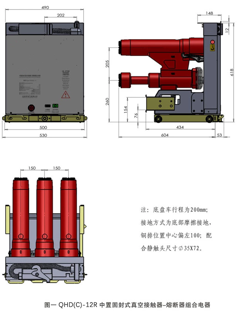
◆ Product Dimensions Diagram
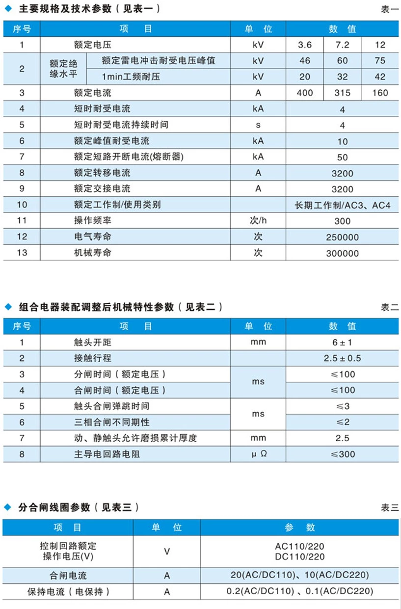
◆ Main Specifications and Technical Parameters
◆ Structural Features
♦ Primary Structure
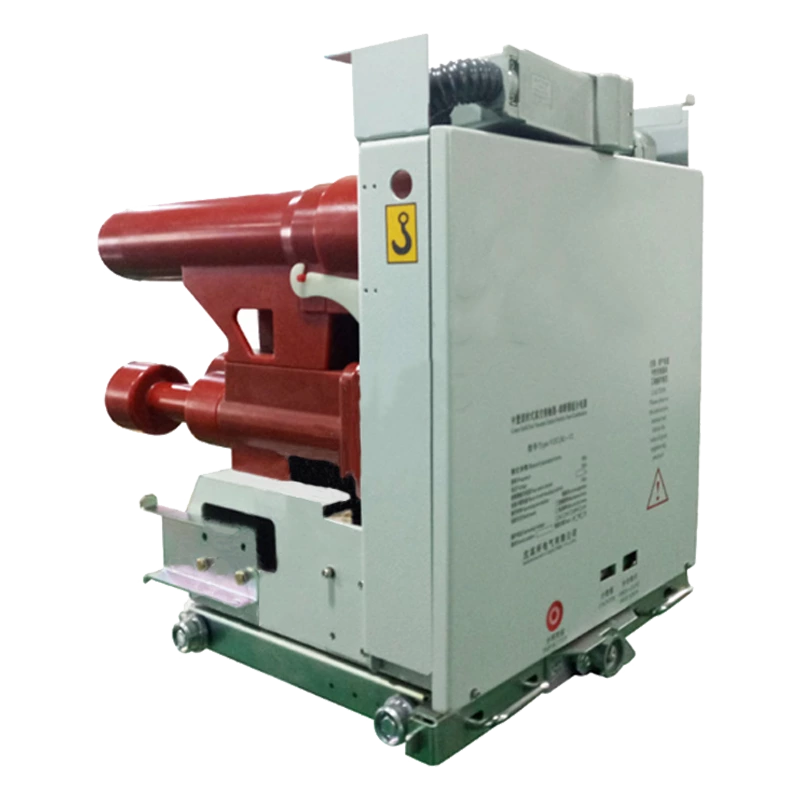
The QHD(C)-12R series combination unit employs a “solid-sealed column” configuration to organically integrate the current-limiting fuse and vacuum arc extinguishing chamber into a series circuit. The contactor body (vacuum arc extinguishing chamber) handles the closing and breaking of various load currents, while the current-limiting fuse handles the breaking of short-circuit currents.
♦ Overall Structure
The combination unit integrates the column and operating mechanism into a unified form, simplifying transmission links. This design aligns the mechanism's output characteristics with the load requirements of vacuum switches, reducing energy consumption and enhancing mechanical reliability.
The three-phase columns are formed using the Automatic Pressure Gel (APG) process. This column structure prevents dust and humidity from affecting the external insulation of the vacuum arc extinguishing chamber, reduces contamination of the chamber housing, and improves overall reliability.
♦ Operating Mechanism
The electromagnetic operating mechanism employs precision magnetic field design and optimized excitation circuits. This ensures reliable closing operation and low long-term power consumption of the electromagnets.
♦ Assembly and Maintenance
The solid-sealed construction and exceptionally stable, reliable operating mechanism result in relatively time-efficient assembly and maintenance procedures.
◆ How It Works
♦ Closing and holding coils not energized
Under the force of the tripping spring, the vacuum arc extinguishing chamber contacts are mechanically pulled apart to an appropriate gap, placing the switchgear assembly in the tripped position.
♦ Closing and holding
Upon energizing the closing circuit of the switchgear, both the closing coil and holding coil activate simultaneously, drawing in the iron block on the drive arm. This transfers force through the main shaft to the insulating tie rod, closing the contacts of the arc-extinguishing chamber. After the drive arm engages, the auxiliary switch de-energizes the closing coil, while the holding coil remains energized to maintain the switchgear in the closed position.
♦ Opening
De-energizing the holding coil eliminates its attraction force. The opening spring then releases stored energy, driving the main shaft to rotate and maintain the switchgear in the open position, thereby completing the opening operation.
♦Fuse Replacement
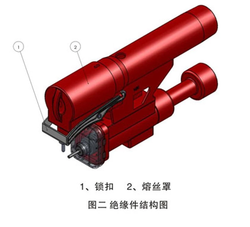
When a fuse blows, the switchgear opens and the fuse indicator switch signals a blown fuse. To replace the fuse tube, slide the handcart out of the cabinet, open the switchgear panel, release latch 1, and firmly pull out fuse cover 2 (see Figure 2).
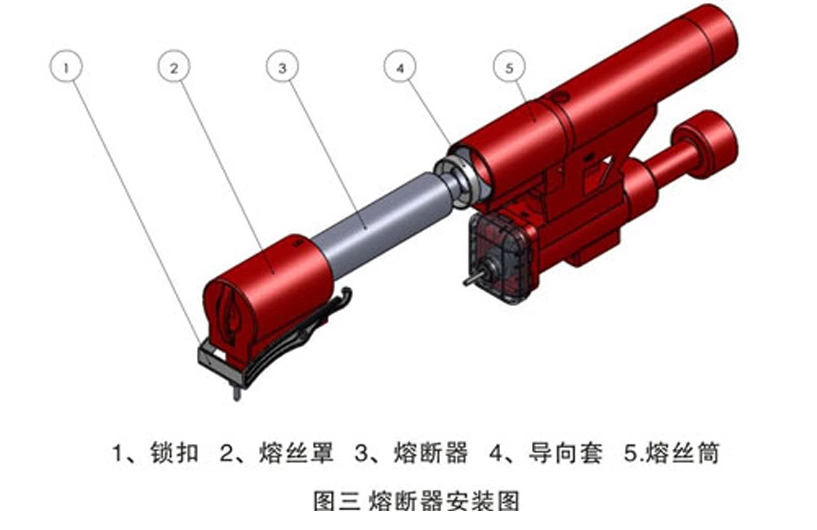
Remove the blown fuse. Insert the pin end of the new fuse into the fuse tube clamp of the fuse cover. Place the fuse (3) with the non-pin end over the guide sleeve (4), then insert it into the fuse tube (5) as shown in Figure 3. Push it slowly until resistance is felt, then firmly push it into place and engage the latch. Secure the rear cover panel with screws to resume normal operation.
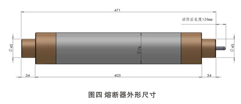
♦Fuse Dimensions
The fuse selected for motor protection shall be of the XRNM1 type. Refer to Figure 4 for its dimensions.
◆ Anti-misoperation Interlocking
a. When the switchgear assembly is not in the test position or working position, the closing circuit is disconnected, preventing closing operations.
b. After closing in the working position or test position, the draw-out unit cannot be moved, preventing withdrawal or insertion into the load compartment while energized.
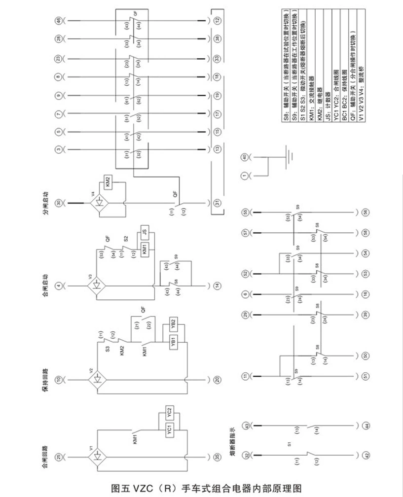
◆ Internal Wiring Diagram of Switchgear Assembly